[diagram] draw and explain circuit diagram for bcd to 7 segment display 4 to 16 decoder circuit diagram Decoder circuit diagram using gates
Implementation of Decoder and Encoder using Logic Gates. - YouTube
2-to-4-decoder logic diagram Design the circuit with a decoder & external or gates Digital and computer system [2]
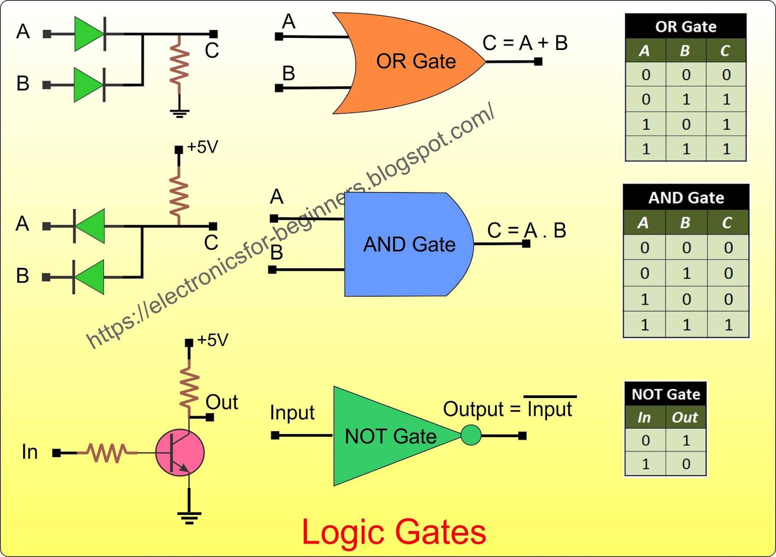
Binary decoder used to decode a binary codes
Full adder logic gate circuit diagram template logic logic gatesSchematic diagram of decoder Circuit diagram creator for logic gatesWhat is a decoder in logic circuits.
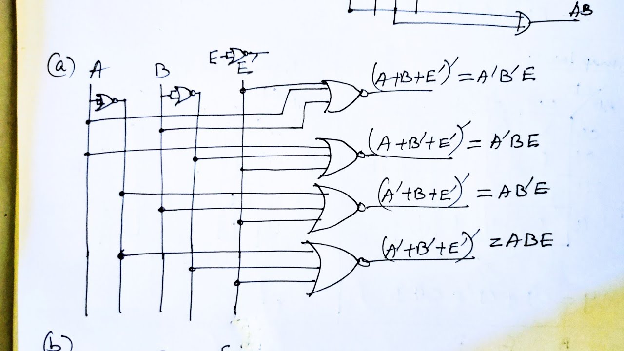
Decoder binary gatesDecoder logic diagram and truth table / ks 0048 logic diagram of 3 to 8 Instrumentation in a nutshell: decoderDecoder logic circuit diagram and operation.
3 to 8 decoder logic diagram
[diagram] relay logic diagramDecoder logic javatpoint coa decoders encoder combinational wiring Logic diagram of 2 to 4 decoder[diagram] logic diagram of bcd to decimal decoder.
Decoder adder 3x8 function multiplexer logic binary inputs outputs block demultiplexer circuits nand designing segmentDecoder implementation using logic gates 3-to-8 line decoder.Decoder logic circuit diagram and operation.

Decoder binary logic digital truth table output geeksforgeeks ab values will q2 q1 q3
4 bit calculatorDecoder logic circuit diagram and operation Decoder logic circuit diagram and operationBinary decoder in digital logic.
Virtual labsHow to design a 4 to 16 decoder using 3 to 8 decoder 4 to 16 decoder using 2 to 4 decoder verilog codeDecoder binary nand line gate codes.
![Digital and Computer System [2] - Combinational and Sequential Systems](https://i2.wp.com/www.elprocus.com/wp-content/uploads/2-to-4-Decoder-Circuit-1.jpg)
Decoder circuit courses amaral webslides webdocs ualberta cs ca logic diagram img027 gif constract ram help circuits
3 to 8 decoder logic diagramDecoder logic rangkaian output equations instrumentation decodificador input vlsi nutshell demultiplexer combinational verilog circuitos inputs encoder bcd ingressi integrato coding Decoder logic gates implementation usingBinary decoder.
Decoder circuit diagram using gatesImplementation of decoder and encoder using logic gates. .

Virtual Labs

Decoder Logic Diagram And Truth Table / Ks 0048 Logic Diagram Of 3 To 8

2-to-4-decoder logic diagram

4 to 16 decoder using 2 to 4 decoder verilog code - snoviva

Implementation of Decoder and Encoder using Logic Gates. - YouTube

Binary Decoder used to Decode a Binary Codes

Design the circuit with a decoder & external OR gates | Intro. to Logic
![[DIAGRAM] Logic Diagram Of Bcd To Decimal Decoder - MYDIAGRAM.ONLINE](https://i2.wp.com/i.stack.imgur.com/DLpzt.png)
[DIAGRAM] Logic Diagram Of Bcd To Decimal Decoder - MYDIAGRAM.ONLINE